

Cylindrical Battery Liquid Injection Machine
5.0
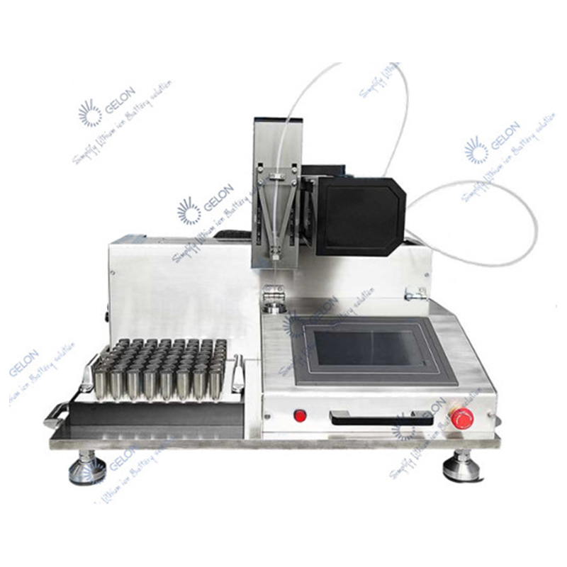
Read 432 reviewsSystem configuration:1. One frame, made of stainless steel and aluminum alloy;2. The automatic lifting device has 2 working stations, including a pneumatic controlled spring lifting device;3. 2 sets of vacuum liquid injection heads, SS316 containers, and double pneumatic lift double lift shut-off va
17 people are viewing this right now
System configuration:
1. One frame, made of stainless steel and aluminum alloy;
2. The automatic lifting device has 2 working stations, including a pneumatic controlled spring lifting device;
3. 2 sets of vacuum liquid injection heads, SS316 containers, and double pneumatic lift double lift shut-off valve structure
4. 2 precision metering pumps( model: E2a-d20i) Plunger pump driven by stepping motor and precision ceramic rotary valve. The injection volume can reach 20ml (23.5g). (refer to pump data)
5. Pneumatic control valve assembly, SMC pneumatic control valve module
6. PLC controller, color touch screen
7. All liquid pipes are PFA plastic
System connection:
This machine is designed to be used in the glove box provided by the customer. The main body of the machine will be placed in the glove box, including the frame, liquid injection head, automatic positioning system, metering pump, etc;
The control elements of the machine are placed outside the glove box. Including the control box, pneumatic control valve assembly, etc. The main body of the machine and the control element are connected by air pipes and cables. These pipes and cables are connected through the reserved space in the glove box.
Vacuum source and compressed air should be provided by customer.
Pipelines passing through the glove box: 1 general air inlet pipe, 1 general exhaust pipe, 1 vacuum pipe and 1 pressurizing air pipe (if pressurization is required). The liquid injection pump can be put into or out of the glove box. The control box is placed outside the glove box.
Working steps:
1. Manually place the 2 batteries on the 2 positioning trays .
2. Press the start switch (foot switch) and the battery will
automatically descend
--- translate to the lower part of the liquid injection head
--- ascend
--- seal the capacitor and the liquid injection head
--- automatic liquid injection process
--- after the liquid injection is completed, the battery will descend
3. Manually remove 2 batteries respectively;
4. Place 2 new batteries for the next liquid injection.
Liquid injection principle:
The battery is in sealed with the liquid injection head, and begins to vacuum the interior of the liquid injection head and the capacitor once. After the vacuum extraction is completed, the poppet valve in the liquid injection head descends to close the channel between the liquid injection head and the battery, releasing the vacuum in the liquid injection valve. At this time, the interior of the tank maintains a high vacuum state. The liquid injection pump quantitatively injects electrolyte into the liquid injection valve by closing the liquid injection nozzle; Open the poppet valve to suck electrolyte into the battery.
Depending on the vacuum degree and the internal density of the battery, multiple vacuuming and liquid suction procedures can be set to vacuumize the liquid injection head again, pass the atmosphere or maintain the pressure until all the electrolyte is injected into the battery. The duration can be determined according to the wetting time requirements of the battery. The air in the battery is evacuated and the electrolyte is fully absorbed into the cell of the capacitor.
Parameters:
1. Liquid injection volume: 0-20ml, accuracy ± 1%
2. Battery Specification: 21700 / 26650 / 32650.
3. Capacity speed: according to the normal liquid injection procedure, PPM = 2pc
4. Power supply: 220V AC
5. Air supply: 75 PSI
6. Vacuum: provided by the customer
7. Pressure gas supply: provided by the customer
You May Also Like
injection machine
Cylindrical Battery Liquid Injection Machine
sealing machine
5 In 1 Sealing Machine(Split)

sealing machine
4 In 1 Sealing Machine(Split)
sealing machine
Manual Corner Sealing Machine
winding machine
Semi-automatic Winding Machine
sealing machine
6 In 1 Sealing Machine(Split)
sealing machine
Manual Top Sealing Machine (Split)
sealing machine
